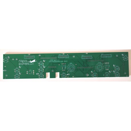
It controls the following inputs:
- encoders: IAS, HDG, V/S and ALTITUDE and their buttons
- rotary switches: BANK ANGLE and ALTITUDE
- buttons: A/Ps, CLB/CON, A/T, LANV, VNAV, FLCH, HOLDs, VS/FPA, LOC/FAC, APP, XFRS, IAS-MACH, HDG-TRK and V/S-FPA, A/T ARMs, F/Ds and A/P DISENGAGE switches
outputs:
- leds of each illuminated butto
and displays:
- IAS, HDG, V/S and ALTITUDE with their announcers
Necessary components (optional). It includes all the necessary components for the MCP panel:
- 26 2-pin polarized female connectors
- 15 polarized 2-pin male connectors
- 1 3-pin female connector
- 12 pushbuttons OMROM B3F 4050 or equivalent
- 2 EC11 encoders
- 2 rotary switches with 12 positions
- 8 x20-pin female IDC connectors
- 10 x20-pin male IDC connectors
- 3 x40-pin male IDC connectors
- 12 spacers 30 mm male-female
- 12 spacers 30 mm female-female
- 18 M3x10 bolts
- 6 M3x15 bolts
- 6 M3x12 black stamped head bolts
- 6 M3 nuts
- 18 plastic washers for M3
- 12 resistors 470 ohms
- 1 terminal strip
- 12 high brightness 3mm white leds
- 6 black push button
- 4 ON-OFF toggle switches
- 1 big ON-OFF toggle switch
- 4 white 6-digit 7-segments displays
- 4 PCBs for 7-segments displays
- 12 plastic bars 3x3x103 mm
- 2 stops for 8 mm shafts
- 2 aluminum shafts diam 8, length 80 mm
- 1 piece for encoder and 6 mm shaft connection
- 1 plastic shaft diam 6
- 2 plastic shafts diam 4, length 12,5 cm
Assembly instructions here.
In order to build MCP panel like shown in the video below, you need to order:
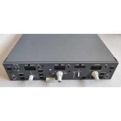
- MCP panel
- MCP PCB with components
- ribbon cable
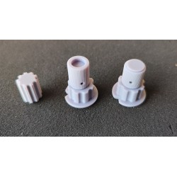
- knobs for MCP
Panel assembly video tutorial:
Video tutorial on mounting the panel in its MDF wood module: