 |
 |
 |
 |
 |
 |


This assembly tutorial is licensed under a Creative Commons Attribution-NonCommercial-NoDerivs 3.0 Unported License.
With this tutorial you'll be able to build an annunciator for any panel or module.
You can find the needed parts here:
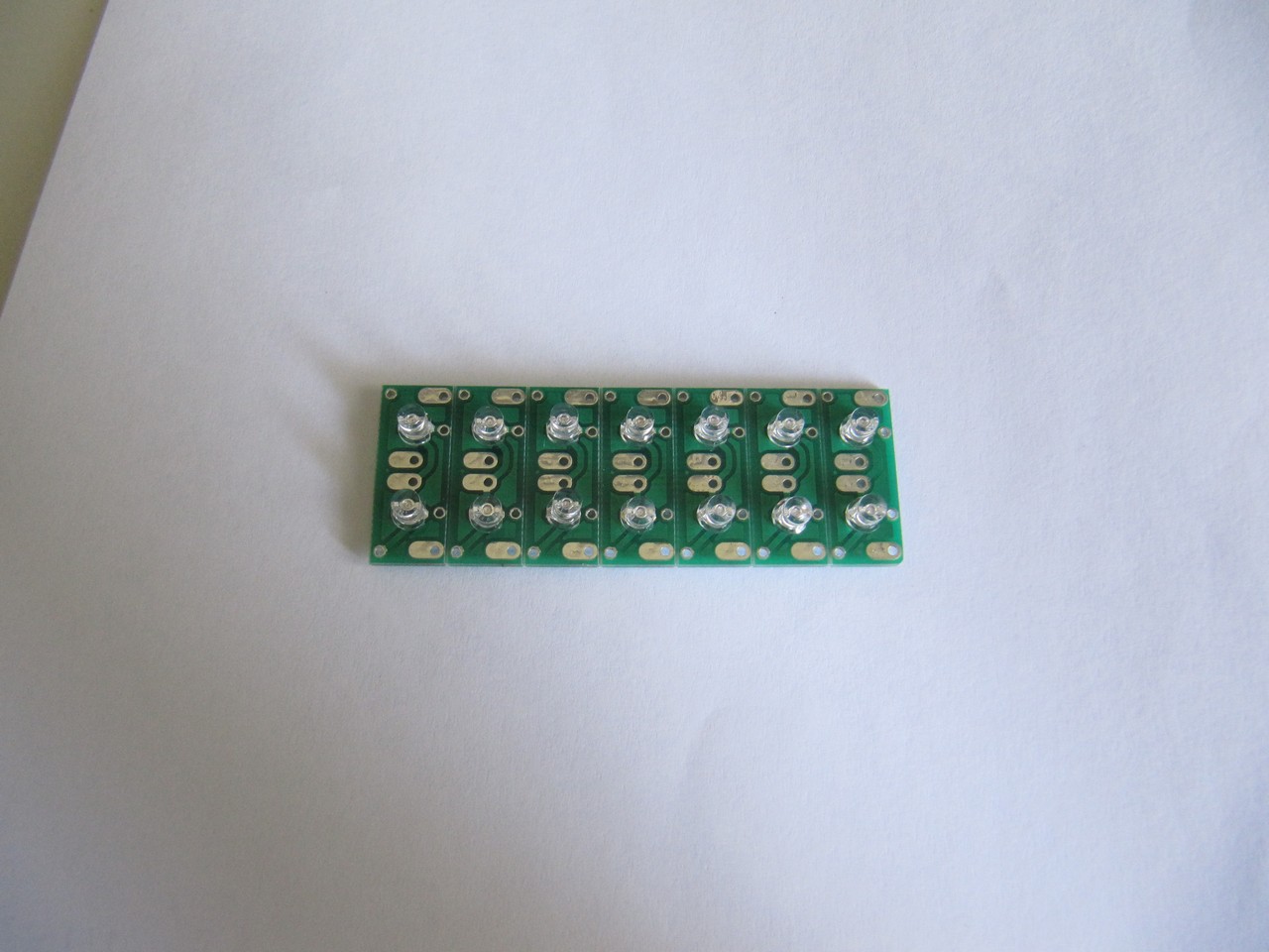
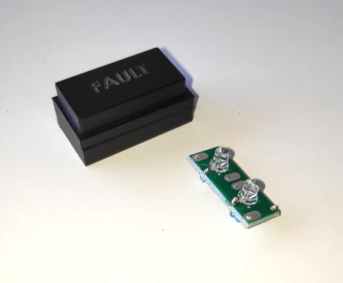
Here you can see the front and the rear sides of the printed circuit board:
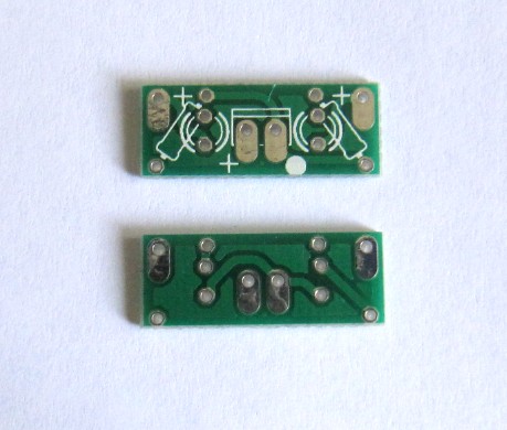
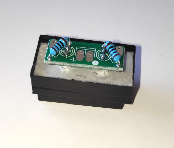
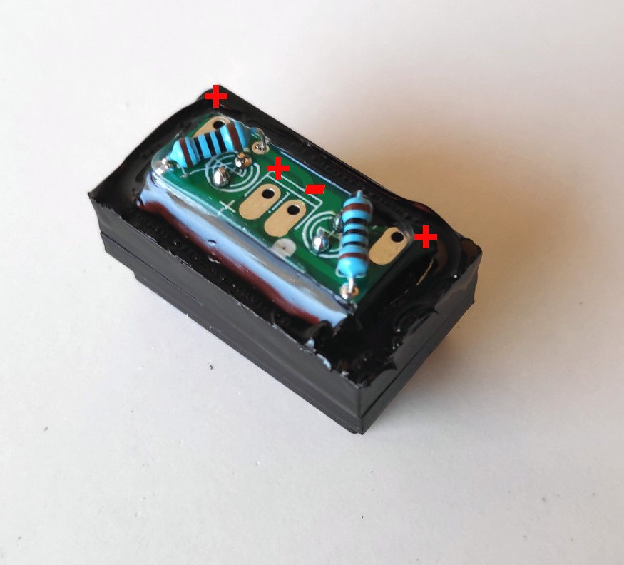
In the center you can install a 2-pin connector (anode is marked with +). You have additional anodes connections on the corners, in order to connect one annunciator with the one besides. The pin that turns ON and OFF the leds is the cathode, marked with a white circle.
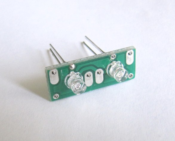
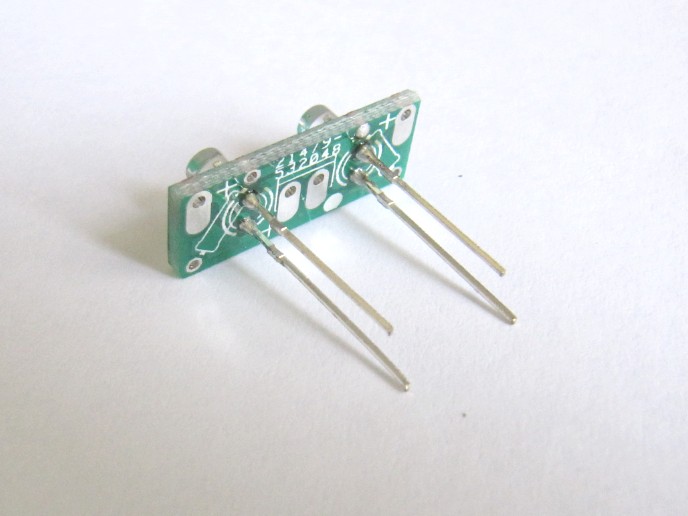
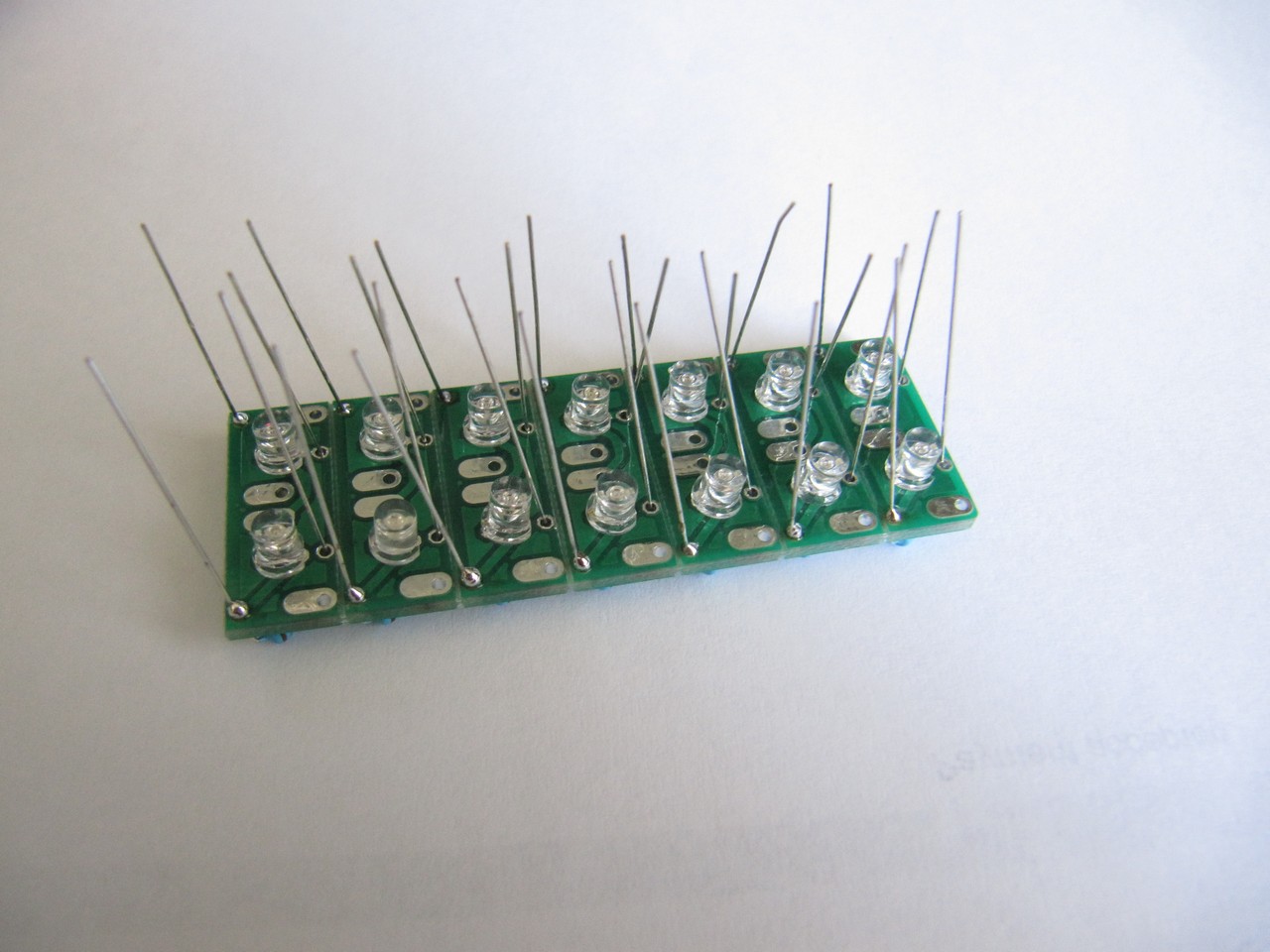
Leds are installed on the back side. This picture shows the position of the leds. The flat part corresponds with the cathode.
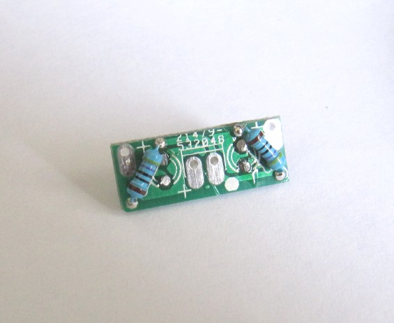
Once the leds are installed, we install a couple of 470-ohms resistors on the front side. Remember this resistor is used when the voltage is 5 vDC (if voltage is different, you'll have to change the resistor value accordingly).
The process is easier if we work with several circuits at the same time.
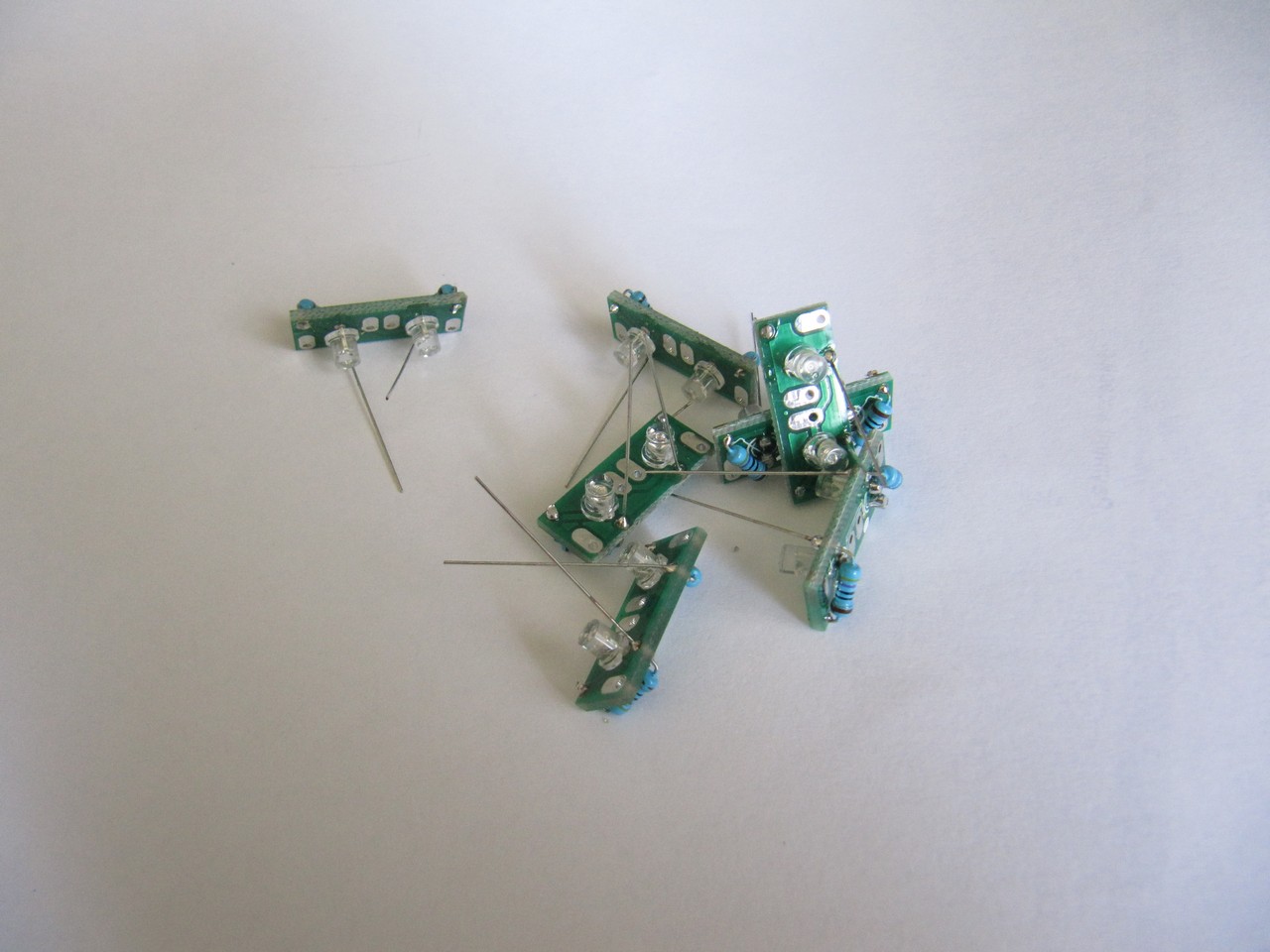
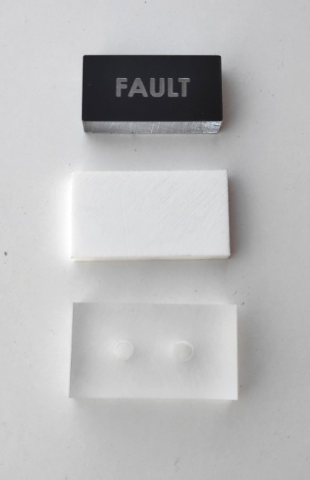
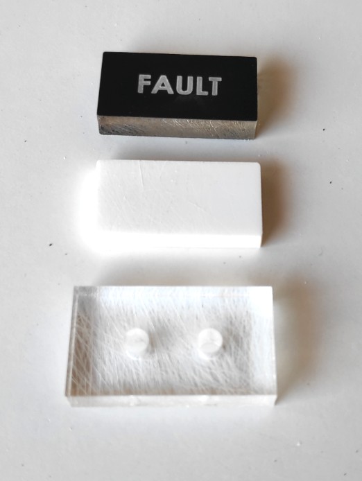
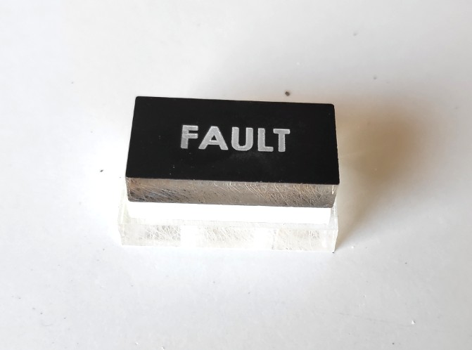
Once we have the leds ready, we can build the annunciator. It consists on three pieces, glued together with acetone or Acrifix (caution: do not damage the paint with acetone or Acrifix).
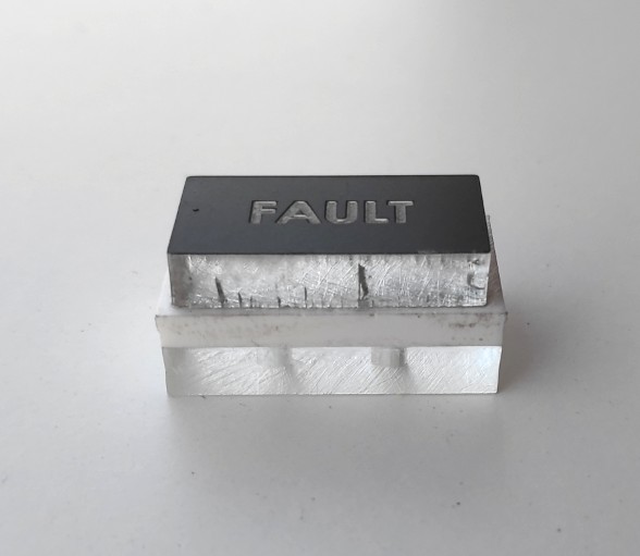
Then we can paint the lateral sides:
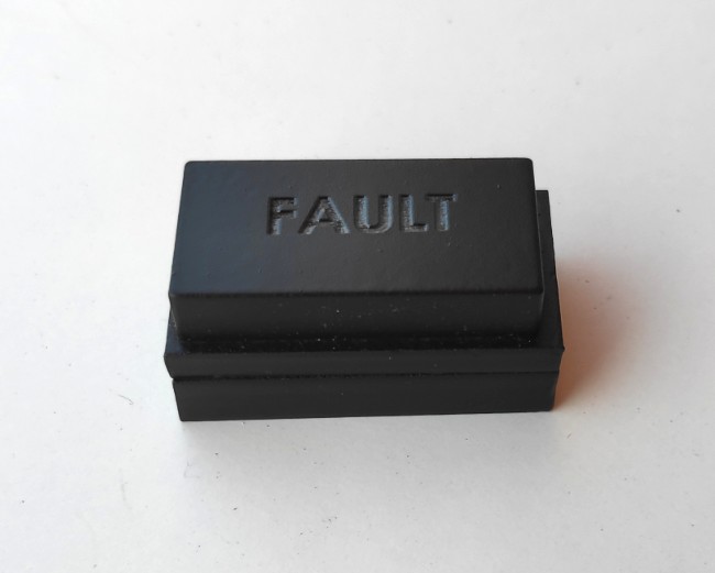
When paint is dry, you can insert the leds and put some thermoplastic glue around the printed circuit board:
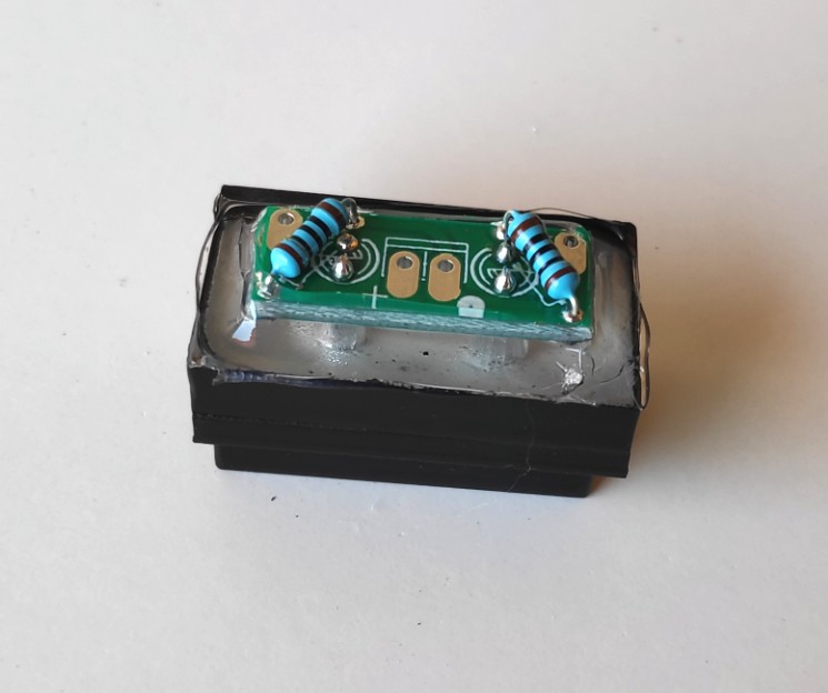
And finally paint the thermoplastic glue in black:
The previous annunciator is the one placed behind any panel. In the case the annunciator has to be placed on a MDF module, the pieces to use would be these ones, being the white one the same size as the top one:
Last edition: 14.10.2021
![]()
![]()